Generating meshes using the FreeCAD standard algorithm
Meshes are a way to model 3D shapes as a set of basic faces, delimited using edges and points.
Usually, it is not the usual core representation of shapes used in 3D CAD softwares because it does not allow modeling exact geometries
in the form of parametric curves and surfaces (such representations are called Boundary Representation or BRep). Nevertheless, their simplicity (only points, line segments and simple faces are used to represent a shape)
has made meshes the representation of choice for many applications like rendering, slicing for 3D printing, etc.
We purposely did not mention the use of meshes to perform FEM (Finite Elements Method) analyses,
as in this case meshes are no longer used for their simplicity, but for their ability to carry and propagate information through bodies.
Most CAD parametric modeling software offer mesh generation and manipulation possibilities, and FreeCAD makes no exception.
FreeCAD hosts a workbench dedicated to working with meshes that offers many useful tools and functionalities,
and we will focus on the one allowing to generate meshes from FreeCAD shapes: Mesh_FromPartShape.
The Mesh workbench icon
The Mesh_FromPartShape function icon
Meshing algorithms and parameters
The function allows using four different meshing algorithms, namely: Standard, GMSH, NetGen and Mefisto. We will focus on the first one, as the three other are dedicated to FEM analyses meshes, and are not in-house.
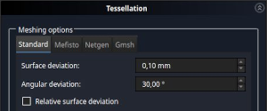
The Standard algorithm
Although the generation process may seem straightforward using the Standard algorithm,
3 parameters are accessible that have great impact on the aspect of resulting meshes, and that are not trivial to understand.
The goal of this post is to provide an insight of how meshing works and can be set-up from a high level point of view,
without entering in details into the complex operations occurring during the generation of meshes.
The standard algorithm stands for the meshing algorithm provided by OCCT, FreeCAD’s geometric modeling kernel.
This algorithm generates surfacic unstructured meshes and basically works in two steps:
Edges of the shapes are first discretized, meaning that curves are transformed into polylines (thus closed contours become polygons),
Then, surfaces are tessellated, meaning they are covered using geometric shapes, triangles in our case.
Generating a mesh from a shape is a complex operation, and implies hidden actions and parameters,
which can lead to behaviors that are not trivial to understand, in particular regarding the setting of the 3 parameters we have access to.
Let’s have a look at their influence with practical examples to better understand how to define good set-ups,
and eventually generate good meshes.
Angular Deviation
The angular deviation is mainly used at the edges discretization step.
This parameter helps ensure the smoothness of polylines that represent curves by avoiding the creation of sharp angles between
consecutive line segments. Edges discretization has a great impact on the overall meshing of the shapes,
because points (at the transition between line segments) generated at this step will serve as basis nodes for the construction of triangles
that will further be used to tessellate faces delimitated by the edges.
This parameter value is relative regarding the size of the shape to be meshed: whatever the size of the shape,
a high angle value may lead to sharp transitions between consecutive line segments, whereas a low value will ensure smoother ones.
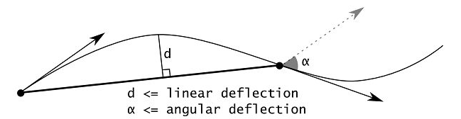
Angular deflection and linear deflection as depicted in OCCT documentation
To illustrate the behavior of the standard algorithm regarding angular deviation,
let’s vary this parameter while meshing a simple circular surface. As the surface deviation parameter also plays a role in the process,
it has been set to a value high enough to avoid any interference with our demonstration: our circle diameter is 50mm,
and so is the surface deviation.
Top: Original BRep circular face (blue) delimited by outer circle (red)
Bottom: Top left detail
Surface deviation: 50mm
Angular deviation: 90°
Surface deviation: 50mm
Angular deviation: 30°
Surface deviation: 50mm
Angular deviation: 5°
Reducing angular deviation have a significant influence on the aspect of the mesh, limiting sharp angles when representing the face contour.
If it allows increasing the fidelity of the mesh regarding the original shape,
it does not give an absolute value of the maximum deviation that has been tolerated between both.
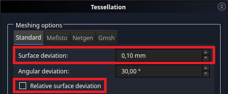
Surface Deviation
To do so, surface deviation is a better pick. It allows specifying the maximum deviation the mesh should be present compared to the original shape.
Let’s get back to our circular surface to understand its influence.
Surface deviation: 50mm
Angular deviation: 90°
Surface deviation: 10mm
Angular deviation: 90°
Surface deviation: 1mm
Angular deviation: 90°
Surface deviation: 0.1mm
Angular deviation: 90°
The influence of surface deviation is clearly visible and easily understandable in our example due to its absolute nature.
It is particularly visible close to the edge: high values (50mm - 10mm) have no impact, whereas many triangles are added to ensure the 0,1mm tolerance.
Angular and Surface Deviation Combined Influence
It can be noted that decreasing either angular deviation or surface deviation has a similar impact on the mesh.
This redundancy can lead to undesired behaviors when bad combinations of these parameters are used:
the following example shows the generation of unnecessary and strangely shaped triangles when setting both angular and surface deviation at low values.
Surface deviation: 10mm
Angular deviation: 30°
Surface deviation: 3mm
Angular deviation: 7°
Surface deviation: 1mm
Angular deviation: 5°
Surface deviation: 0.1mm
Angular deviation: 1°
A First Synthesis
The above examples shows that it is possible, using angular and surface deviation,
to obtain meshes that are in a requested tolerance compared to the original shape, and achieve desired smoothness when representing curves.
They also show the importance of an adequate setting, and that simply setting low values may not produce the best meshes as a result.
The devil is in the details
If our circular shape gave a good understanding of the parameters' influence on mesh generation,
it is unfortunately too simplistic compared to real-life meshing challenges.
A common case is the presence of fine details on bigger shapes. Let’s add a detail to our circular shape,
in the form of a smaller circular edge at the top.
BRep circular face (blue) with a circular detail at the top
Close view of the circular detail
Angular deviation /
Surface deviation
90°
30°
5°
5mm
Nb of triangles
10
32
149
1mm
Nb of triangles
18
34
188
0.1mm
Nb of triangles
53
59
207
Angular deviation /
Surface deviation
90°
30°
5°
5mm
Nb of triangles
10
32
149
1mm
Nb of triangles
18
34
188
0.1mm
Nb of triangles
53
59
207
Lowering angular deviation leads to a rapid fidelity increase between the mesh and the original shape. This is done at the expense of rapidly increasing the number of triangles.
On the other hand, lowering the surface deviation allows generating meshes that just fit a requested tolerance, with just as many triangles as needed,
but the smoothness of curve representation may be crude.
Again, one may note the redundancy between angular and surface deviation respective influences,
and that some sort of convergence is achieved regarding the mesh fidelity even if more triangles are added, in particular when lowering angular deviation.
This underlines once again the fact that finding a good setting is better than simply choosing a low value for the parameters.
Hidden Parameter example
It can also be noted that high values of surface and angular deviations do not lead to the suppression of the detail at the top of our shape
within the mesh modeling.
This is an example of the effect of hidden operations and parameters within the meshing algorithms: particular types of edges,
and circular edges among others, have a lower limit of points for their polyline representation. In this case,
the minimum of 4 points will result in at least three segments within the polyline. This can be highlighted by meshing a similar shape,
but instead of a circular curve, a spline has been used to model the detail at the top. The minimal number of points then does not apply,
and the detail is totally inhibited when high values of surface deviation are used.
Geometrical nature of the detail
The shape
The mesh
A close view
Arc of circle
Spline curve
A Second Synthesis
These examples including details within bigger shapes, which are very common in real life,
stress the fact that adapting the precision of discretization to the size of entities to be meshed may lead to better trade-offs between mesh precision and complexity.
Sometimes it can even be mandatory, for instance when performing automated meshing operations,
where a user intervention to set up the surface deviation according to shape size is not possible.
Relative Surface Deviation
A solution is to set the surface deviation as a function of the edge length, which is achieved using the relative surface deviation parameter.
The principle is to scale the acceptable tolerance between the mesh and the original shape as a function of the size of the shape.
For instance, a value of 0.1 will lead to a surface deviation of 10cm on a 1m edge, and a 1m surface deviation on 10m edge.
Let’s take a look on the results on our test shape.
Relative surface deviation parameters
Surface deviation (relative)
& Angular deviation
The mesh
A close view
A closer view
0.1 - 30°
0.001 - 30°
The evolution of the surface deviation parameter (which is now a relative parameter, so the ‘mm’ unit when setting it in FreeCAD may be confusing)
applies the same way to the discretization of both the long and short edges.
The side effect of using the relative surface deviation is that it does not guarantee an absolute maximum deviation between
the mesh and the original shape.
Surface Tesselation
Our first thoughts essentially focused on shapes contours, because they are the first entities to be discretized, and have a great influence on the meshing of faces.
Let’s dive a little bit more in surface tesselation using the standard algorithm. It applies Delaunay triangulation, using the Watson algorithm.
Delaunay (from a Russian mathematician) triangulation is a way to generate points on a surface in a way that ensures triangles formed using the points will not intersect.
In addition, it optimizes the generation of triangles in a way that they do not present tiny angles, so they look like well-shaped triangles.
That being said, as often, practical implementation to address real-world problems is complex and presents many challenges.
OCCT meshing algorithms have been designed to mesh shapes generated with the BRep modeler, most often mechanical and engineering designs,
which were the usages the geometric modeler was initially developed for.
Thus, dedicated surface tesselation routines are used for the most common surface types in mechanical design, e.g. planar, cylindrical, conical, spherical, …
to ensure performance and optimal tesselation. If the parameters settings have an impact on every surface type,
let’s have a look at their influence regarding BSpline surface tesselation, to avoid biases from predetermined tesselation strategies.
A BRep shape with BSpline surfaces
Angular deviation /
Surface deviation
90°
30°
5°
5mm
Nb of triangles
196
666
9730
1mm
Nb of triangles
376
790
26128
0.1mm
Nb of triangles
3002
3262
36366
Conclusions are in accordance with what we saw with faces: angular deviation shows a great impact on the mesh aspect,
while surface deviation guarantees a fidelity level at the lowest cost in terms of mesh complexity, but generates visible facets.
Thus, a trade-off is to be found between the quality of the mesh regarding fidelity and smoothness, and the size of the mesh in terms of the number of triangles.
If you are curious about the impact of growing the number of triangles, you can have a feel by playing with the Minimum angular deflection parameter of your favorite software
(Edit -> Preferences -> Part/Part Design -> Shape view) which defines the fidelity of meshes used for visualization.
A too-low value will lead to higher loading times and jerky view manipulations for complex shapes.
Another way to perceive the impact of parameters is to transform our meshes into real objects by 3D printing.
Resin printing (SLA) using 0.05mm layer height will allow revealing some details.
Surface deviation &
Angular deviation
0.1mm - 90°
5mm - 5°
0.1mm - 5°
Surface picture
Surface picture
Nb of triangles
3002
9730
36366
These close-up pictures reveal that caring only about surface deviation, even at low values, may lead to visible artifacts on the surface of the part
(as the zoom level is high, meshing impacts are not to be confused with printing layers, which are also visible as iso-lines on the pictures).
It is difficult to differentiate the 9730 triangles mesh from the 36366 triangles one in terms of visual quality.
Then, if it is the criteria, the lighter mesh (487ko VS 1.8Mo) should be preferred, the other one giving insurance the 0.1mm tolerance is respected everywhere in the part.
A Last Synthesis
As a synthesis, meshing algorithms are complex by nature, and angular deviation and surface deviation are working together in an intricate way that is not trivial to understand.
One could be tempted to lower these parameters so the mesh fits seamlessly to the original BRep shape.
This would lead to meshes made of many triangles, that will take time to be generated, to be processed in further applications, and will produce heavy files.
Parameters set-up workflows
From what we saw, a typical workflow to set the parameters is to first set surface deviation as a function of required fidelity between the mesh and the original shape,
if any. Then, the angular deviation parameter can be used to adjust the smoothness of discretized surfaces to the required level, for visual or touch aspect for instance.
Another approach is to use a low enough angular deviation in order to achieve desired smoothness, with no guarantee to fulfill an absolute geometric tolerance,
and often at the cost of complex meshes. In those case where no tolerance on fidelity is needed, another option is to use the relative surface deviation,
which will adapt the size of the mesh elements to the original shape and details size.
Setting your meshing set-up as FreeCAD default
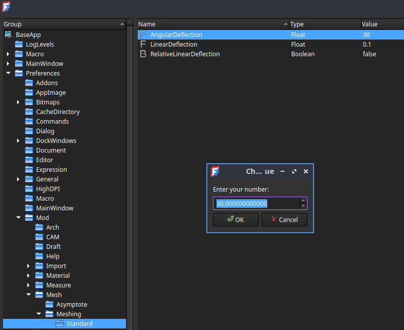
As explained in the Preferences section of the function wiki,
you can define your preferred surface deviation, angular deviation and relative surface deviation values as default,
so you can mesh most of your shapes without event thinking about it!
Default settings for standard algorithm parameters
Export your meshes
Once meshes have been generated with the adequate parameters,
you can eventually extport it to a file in the format of your choice among the several options FreeCAD offers!


)
)
)
)
)
)
)
)
)
)
)
)
)
)
)
)
)
)
)
)
)
)
)
)
)
)
)
)
)
)
)
)
)
)
)
)
)
)
)
)
)
)
)
)
)
)
)
)
)
)
)
)
)
)
)
)
)
)
)
)
)
)
)
)
)
)